Anybody who has a little bit of understanding of modern automation systems can vouch for the importance that servo motors hold in this realm. Servos are almost non-negotiable when it comes to delivering high precision, rapid response, and accurate control of repetitive motions across different automated sectors and industries.
Take CNC machines, robotics, packaging lines, or conveyor belts as major examples. Servo solutions have been powering them through and through, ensuring enhanced precision and speed with each passing year. But have you ever wondered what makes servos so special that the performance and existence of modern automated systems and industries are almost non-existent without them?
Well, the core power and performance of any servo lie in its winding structure. This structure directly influences overall torque generation, speed, efficiency, control, repeatability, and accuracy of any setup. Anybody who wants to fully understand the working of a servo unit and how it maintains its efficiency needs to understand its winding structure first.
One must accurately read and interpret this structure to understand the system’s performance and how it works. This understanding is also important for anyone who wants to learn how to troubleshoot, repair, and optimize a servo solution for personal projects. Engineers who want to accurately read and interpret servo performance must also know how to read servo motor windings diagrams.
Servo motor windings diagrams, contrary to what their name suggests, are not merely a schematic drawing. Rather, it visually represents the core working and assembly of the system. This diagram shows how coils are arranged, electrically connected, and grouped within the motor. It also illustrates phase relationships, terminal connections, and the path that the current follows inside the assembly.
For technicians and engineers who work closely with and optimize industrial setups that have servos at their heart, these diagrams are not just blueprints to read. Instead, they are technical roadmaps that guide them in installing, controlling, integrating, rewinding, and maintaining their servos. Misreading even a single symbol or phase sequence in such diagrams can lead to wiring faults, motion instability, overheating, and downtime.
Many often dread servo motor winding diagrams because of their complex appearance. Especially for beginners, these visually heavy diagrams can be intimidating. Unlike standard induction motors, servo solutions use specialized winding designs to optimize precise feedback control, which further adds to the difficulty of interpreting their diagrams.
If you also want to learn how to understand and read a servo motor winding diagram, you are at the right place. This guide is a practical and comprehensive resource that simplifies the overall process of decoding and understanding servo motor winding diagrams.
Below, we will break down the fundamentals of a servo system, along with explaining common symbols and notations that one must be aware of to read these diagrams correctly. After reading this article, automation engineers, technicians, and students will be able to confidently and clearly analyze winding diagrams and apply that knowledge to real-world applications.
Fundamentals To Understand Servo Motor Windings Diagrams
One cannot begin to understand servo motor windings diagrams without first knowing the fundamentals of the actual windings. So, before we start explaining the symbols and core components of any servo diagram, it is important to understand what makes up its winding system.
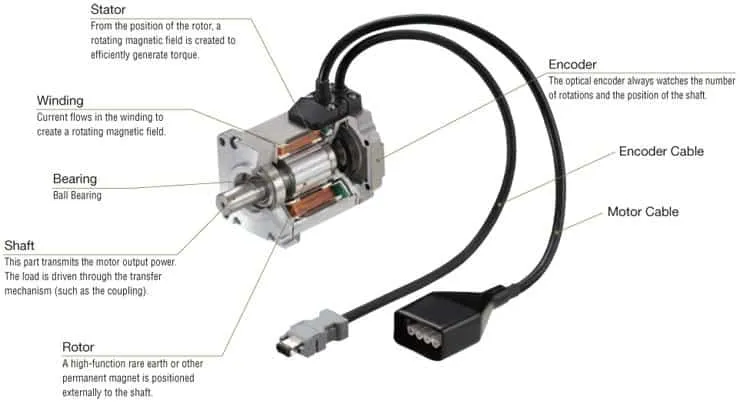
Windings are basically copper coils placed inside the stator slots, where they generate a controlled magnetic field when energized by the external drive. The magnetic field that is generated interacts with the rotor of the motor to produce precise motion, thus making winding design a key factor in precision motion. This makes windings a critical element in a motor’s working accuracy, torque, and speed production, as well as its response time.
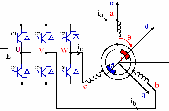
Most servo solutions use three-phase windings. In such windings, current is supplied in a carefully controlled sequence. Compared to conventional motors that operate at fixed speeds, servo windings are designed to handle continuously changing current levels. The design of these windings allows the system to deliver exact torque and position control and to ensure corrective measures based on feedback from encoders or resolvers.
Another important determinant of motor characteristics is the arrangement of windings inside the stator. This arrangement affects torque ripple, efficiency, heat dissipation, and speed maintenance in a noticeable manner.
Properly balanced windings are important to ensure smoother rotation, reduced vibration, and consistent performance output across changing loads. Here, the quality of installation as well as the size of the conductor is also important.
Whenever you try to read a servo motor winding diagram, understanding all these fundamentals is important, as it helps you identify the distribution of coils as well as phase formation inside the housing. This understanding also helps one see how electrical energy is converted into mechanical motion in any kind of motorized setup.
An Important point to note before we begin understanding the reading phase of any diagram is that related to winding configurations. It often varies based on the application requirements of the motor.
A common configuration is distributed windings, where coils are spread across multiple stator slots to ensure a smoother magnetic field. Another configuration is concentrated windings, where coils are closely grouped within fewer stator slots. This approach is used when a compact housing design is required that must produce high torque and operate at a non-negotiable speed.
Depending on the motor application, there may be differences in how windings are connected electrically within different housings. Some use star (Y) connections, while others use delta (Δ) connections to ensure higher-speed operation. Star connections are ideal when a setup needs to achieve high torque at lower speeds, while delta connections work best for high-speed operations. These configurations are clearly indicated in winding diagrams and directly influence the overall working of a motor.
Once you understand these configurations and are able to clearly read them in diagrams, you can easily trace motor issues arising from incorrect configuration, misinterpretation, or other installation faults.
Key Symbols and Notations in Winding Diagrams
Regardless of the manufacturer that provides them or the kind of application they are used for, almost all winding diagrams have standardized symbols and labels that one must understand to clearly read and interpret these diagrams.
These symbols often represent coils, phases, as well as the electrical connections between different windings and components inside the assembly. Correctly interpreting these symbols helps ensure accurate wiring, installation, configuration, and troubleshooting.
Below, we are dividing these major symbols and labels into different groups to help you further expand your knowledge.
1 Phase Identification Symbols
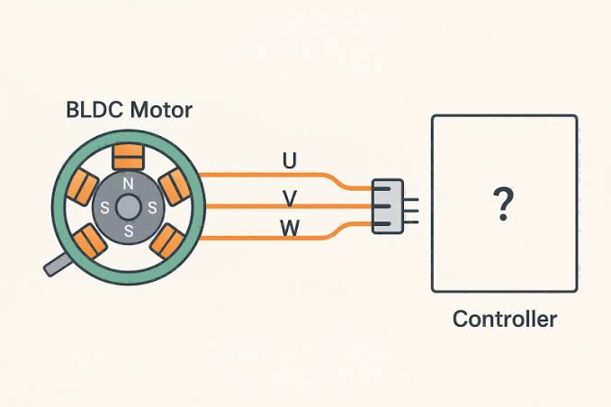
Phases are usually labeled with English letters such as U, V, W, or A, B, C. These labels are used to indicate different winding groups that must be energized in a specific sequence to ensure correct rotation, torque generation, and desired speed output from the motor.
2 Coil Start and End Markings
Coil terminals are often marked with symbols such as U1 – U2, V1 – V2, and W1 – W2. These markings help identify the start and end points of each coil, enabling technicians and engineers to maintain correct polarity while making connections.
| Symbol | Meaning |
| U, V, W | Three-phase windings |
| U1–U2 | Coil start and end |
| ● | Electrical junction |
| × / ⊗ | Current direction indicator |
Most of these symbols form the foundation of any motor winding diagram. Understanding and memorizing them is important for engineers who want to trace electrical paths accurately and avoid confusion in their projects.
3 Connection and Junction Symbols
Dots, lines, and node markers indicate electrical junctions where coils are connected. Dots, node markers, and lines in a diagram indicate electrical junctions within the motor. At these points, coils are connected.
Crossing lines without dots usually means there is no electrical connection. This is an important source of misreading and often leads to wrongly interpreted diagrams, so it must be handled with care.
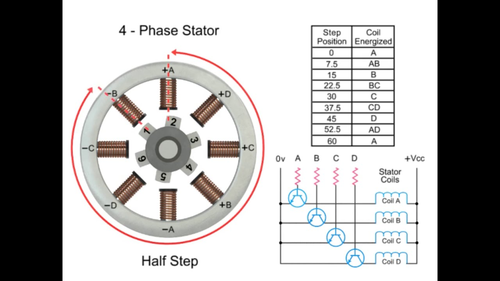
4 Direction and Current Flow Indicators
Each servo motor winding diagram includes arrows, dots, or cross symbols that represent current direction or magnetic polarity. These indicators help visualize phase sequences and electromagnetic interactions inside the motor. The table below visually represents the connection configurations and how to read them.
| Connection | Purpose |
| Star (Y) | Higher torque at lower speed |
| Delta (Δ) | Higher speed capability |
Mastering these symbols and notations is usually the first step toward confidently decoding any motor winding diagram. Once you have learned and memorized these points, you can easily avoid winding errors in your projects that could otherwise compromise overall system performance.
Understanding Coil Grouping and Phase Sequence
In any servo housing, individual coils are not energized separately. Instead, they are arranged into groups to form a complete electrical phase. Each phase consists of multiple coils placed strategically within the stator slots, creating a balanced and symmetrical magnetic field.
Proper grouping of coils ensures smooth torque production with minimal noise and vibration. It also ensures a stable overall operation of the system under changing external conditions.
Phase sequence refers to the order in which current flows through the coil groups or phases. These are commonly represented as U → V → W or A → B → C. This sequence determines the direction of the rotating magnetic field and, as a result, the direction of rotation.
If the phase sequence is altered, the motor may rotate in the opposite direction or behave unpredictably, which is especially harmful in precision applications.
The diagrams usually illustrate how coils are grouped and connected to form each phase. Correctly reading these diagrams helps engineers identify which coils belong to the same phase and how they are positioned relative to one another. Proper phase alignment is extremely important, particularly for setups used in automation, where even minor mistakes or imbalances can compromise positional accuracy and feedback stability.
Understanding coil grouping and phase sequencing enables engineers and technicians to verify correct wiring, troubleshoot rotational issues, and ensure compatibility between the servo and its controller. This knowledge is also critical when maintaining or optimizing a servo assembly.
Reading Servo Motor Winding Diagrams – Stepwise Guide
With proper knowledge of the basic symbols, coil grouping, and phase sequence notations used in generic winding diagrams, one can easily read and interpret these diagrams correctly. By following the steps below one by one, the process of reading any diagram becomes much clearer and more structured.
Step 1: Identification of motor type and phases
Firstly, you have to confirm the type of motor as well as the number of phases shown in the diagram. Most diagrams have three-phase windings labeled as U, V, and W.
Step 2: Locating coil start and end points
Once you are aware of the phases, it is better to locate the terminal markings such as U1, U2, V1, V2, and W1, W2. At this stage, you will become aware of the beginning and end of each coil and will understand the correct polarity of the motor inside the assembly.
Step 3: Understanding coil grouping
Now begin tracing the placement and connections of individual coils within each phase group. The coils usually show a repeating pattern around the stator, which helps identify proper grouping and balance.
Step 4: Checking phase sequence
Follow the order of connections between phases to determine the phase sequence. This helps confirm the intended direction of rotation as well as the direction of current flow.
Step 5: Analyzing connection types
At this stage, identify the configuration of the motor and determine whether the windings are connected in a star (Y) or delta configuration. This knowledge affects your understanding of the motor’s voltage requirements as well as its behavior with respect to current input.
Step 6: Verifying current flow indicators
Lastly, observe the arrows, dots, or polarity symbols shown in the diagram. These indicate the direction of current flow and the resulting magnetic interactions inside the motor.
Once you have completed all these steps systematically, you can easily understand and interpret any winding diagram. This approach also helps reduce the risk of wiring and configuration errors when installing, reconfiguring, maintaining, or repairing any assembly.
Interpreting Winding Diagrams for Different Servo Types
Servo motor windings diagrams may vary slightly depending on the motor type, and understanding these differences helps ensure correct and accurate interpretation without confusion.
In AC servos, the diagram typically shows a three-phase stator winding combined with a permanent magnet rotor. These diagrams emphasize phase symmetry, coil grouping, and precise phase alignment to support smooth sinusoidal current control from the servo drive.
DC servos are less commonly used in modern automation and industrial applications because they rely on armature windings with commutator segments. In their winding diagrams, there is more emphasis on brush connections and coil sequencing instead of phase relationships. To interpret these diagrams correctly, one must pay close attention to commutation paths and current reversal points.
Brushless DC servos fall between AC and DC designs and are widely used. Their winding diagrams often resemble three-phase AC layouts. However, these diagrams may show trapezoidal winding arrangements along with detailed phase identification. Correct phase labeling and Hall sensor alignment are critical in these diagrams to ensure proper electronic commutation.
High-torque or direct-drive servos may use specialized winding layouts that are optimized for low-speed or high-precision motion. In such diagrams, you will often see dense coil groupings and short-pitch windings.
Recognizing the motor type while interpreting winding diagrams allows engineers to focus on the most relevant elements in each visual representation. This helps avoid confusion and misinterpretation that could otherwise affect system performance and reliability.
Common Mistakes When Reading Winding Diagrams
A common mistake when reading any winding diagram is the misidentification of phase labels. It is easy to confuse the U, V, W convention with A, B, C, which often leads to incorrect wiring and reverse motor rotation.
Another frequent error is ignoring coil start and end markings. This results in incorrect polarity and uneven magnetic fields during rewiring or maintenance.
Even experienced engineers and experts can misinterpret crossing lines as electrical connections when no junction symbol is present. Due to this misunderstanding, short circuits and incomplete phase connections are quite common.
Overlooking the specific winding connection type, such as star or delta, is another typical mistake that directly affects voltage levels, current flow, and torque behavior.
Another common issue in reading winding diagrams is assuming that all servos follow the same design and diagram standards. Depending on the manufacturer and type, diagrams may use different symbols, layout styles, or conventions.
This is why it is essential to carefully review the legends and notes provided with each diagram and to recognize symbols exactly as they are intended to be interpreted.
| Common Mistake | What Goes Wrong | Impact on Performance |
| Phase misidentification | Phases wired incorrectly | Reverse rotation or unstable motion |
| Ignoring coil polarity | Magnetic field imbalance | Torque ripple and vibration |
| Misreading crossing lines | Accidental short or open circuit | Motor overheating or failure |
| Wrong Y/Δ assumption | Voltage mismatch | Reduced torque or drive faults |
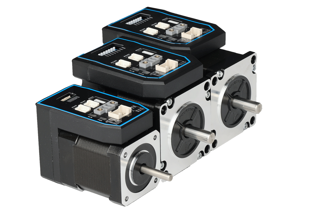
Get Properly Developed Servos With Reliability At Their Core – Connect With DMKE Today!
At DMKE, our experts go far beyond simply assembling a motor. Our engineers possess a strong understanding and technical background in winding diagrams, phase sequencing, and electromagnetic design principles.
This technical expertise is applied throughout the manufacturing and design process to produce impeccable units that undergo rigorous testing after development, ensuring they deliver superior speed, accuracy, precision, and reliability.
By combining advanced winding analysis with strict quality control, we ensure that every motor, whether from our ready-made range or custom solutions, is optimized for efficiency, reliability, and real-world performance.
Visit our website and connect with us to access precisely engineered solutions designed to meet all your industrial, commercial, and individual needs.