Brushless DC Motor
- DMKE
- Brushless DC Motor
Brushless motor, no need to use is generally considered to be the shortcomings of DC motor brush and commutator and mechamical contact DC motor using brush and commutator to rotate, therefore, need regular maintenance, and no brush motor using Hall IC detects the signal, the driving circuit of transistor on / off spin, so there is no need to maintain.
Product Features
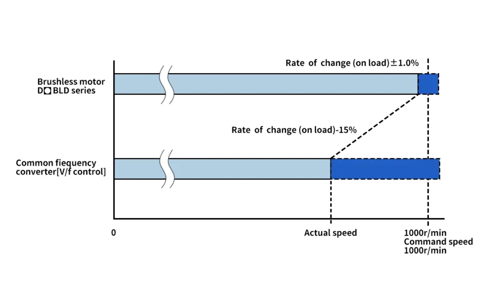
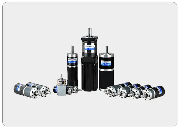
Stable Speed Control
Brushless motor continues to set speed and a feedback signal are compared from the speed of the motor to adjust the voltage applied to the motor; therefore, even if the load change, still can set the speed from slow instantaneous adjustment to, and in order to stabilize the running speed. Three phase induction motor with inverter control is not feedback control, so the load becomes larger, the speed will be greatly reduced; for the high speed stability requirements, it is recommended to use brushless motor.
Thin,High Power
The use of permanent magnet brushless motor rotor, thus realizing the thin and high power; for example, and installation size 90 of the three-phase induction motor is compared to the length of the relationship>75mm, power output reached 1.3 times. lf the brushless motor is used, it is helpful to realize the miniaturization of the device.
Wide Speed Control range
Brushless motor speed control range than speed AC motor and inverter wider, because unlike the speed AC motor that at low speed have restrictions on the use of torque, so there is no brush motor is suitable for from low speed to high speed, all require the use of a certain torque.
| Product Style | Speed Control Range | Rate Ratio |
| Brushless Motor | 80-4000 | 50 |
| Frequency Converter Control 3 Phase Induction Motor | 200-2400 | 12 |
AC Speed Regulating Motor | 50HZ:90-1400 | 15 |
| 60HZ:90-1600 | 17 |
Contribute to energy saving
The rotor of the brushless motor is used for the permanent magnet, which can reduce the two loss of the rotor, so the power consumption is reduced by more than 20% compared with the three phase induction motor with variable frequency control, which is helpful for the energy saving of the device.
| BLDC Motor Without Gearbox | ||||
| Rated Power(W) | 10W to 35KW | |||
| Rated Voltage(V) | DC 12V,24V,36V,48V,72V,96V,310V | |||
| Flange Size(mm) | 42,57,60,80,90,110,130,180,220 | |||
| Rated Torque Range(N.m) | 0.063 to 100N.M | |||
| Rated Speed Range(r/min) | 750 to 25000 | |||
| Remark:Power above 2000W not suitable for high speed motors | ||||
| BLDC Gear Motor | ||||
| Rated power(W) | 10W to 750W | |||
| Rated voltage(V) | DC 12V,24V,36V,48V,310V | |||
| Flange size for gearbox(mm) | 60 | 80 | 90 | 104 |
| Max rated torque(N.m) | 3 | 8 | 20 | 40 |
| Gear ratio: | 3,5,7.5,10,12.5,15,18,20,25,30,36, | |||
| 40,50,60,75,90,100,120,150,180,200,300 | ||||
| BLDC Planetary Gear Motor | ||||
| Rated power(W) | 10W to 35KW | |||
| Rated voltage(V) | DC 12V,24V,36V,48V,72V,96V,310V | |||
| Flange size range(mm) | PLF42 to PLX242 | |||
| Rated torque range(N.m) | 0.5 to 4420N.m | |||
Gear ratio: | 1st stage:3,4,5,7,10 | |||
| 2st stage:12,16,20,25,28,35,40,50,70 | ||||
| 3st stage:64,80,100,125,140,175,200,250 | ||||
| BLDC Worm Gear Motor | |
| Rated power(W) | 10W to 10KW |
| Rated voltage(V) | DC 12V,24V,36V,48V,72V,96V,310V |
| Flange size range | RV25,RV30,RV40,RV50,RV63.RV75, RV90,RV105,RV110,RV130,RV150 |
| Rated torque range(N.m) | 0.5 to 1000N.m |
| Gear ratio: | 7.5,10,15,20,25,30,40,50,60,80,100 |
| Micro BLDC Motor | ||||
| Rated power(W) | 2W to 50W | |||
| Rated voltage(V) | DC12V,DC24V | |||
| Motor diameter range(mm) | 16,24,28,36,42 | |||
| Rated torque range(kg.cm) | 0.1 to 60 | |||
| Gear ratio: | 4 to 720 | |||
| BLDC Motor Controller | ||||
| Rated current range(A) | 3A to 300A | |||
| Rated voltage(V) | 12V to 310V based on different drive | |||
| Selectable communication mode | RS485,RS232 | |||
| Speed adjustment range | 300 to 3000r/min | |||
| Needed information | Motor’s rated power&voltage,ambient temperature,communication method | |||